


Views: 0 Author: Site Editor Publish Time: 2026-10-18 Origin: Site


Mismatched Current Transformer (CT) ratios create massive financial liabilities in high-capacity electrical systems. A single configuration error skews billing data instantly. It also hides dangerous phase overloads from facility managers, leading to blown breakers and melted insulation. Indirect measurement systems introduce multiple failure points that direct-connect meters simply avoid. You must audit these systems rigorously to uncover hidden configuration bugs before you energize the panel. Procurement specifications often misalign with physical CT installations on the shop floor. The internal software configuration of the meter then compounds these physical errors. This guide serves as your definitive engineering checklist. You will learn to specify exact CT parameters, align hardware, and execute comprehensive pre-commissioning verification. We cover the exact field steps needed to ensure absolute measurement integrity before final sign-off.
Ratio Alignment is Non-Negotiable: The physical primary-to-secondary CT ratio must perfectly match both the actual load profile and the programmed multiplier within the meter to ensure accurate kWh data.
Burden and Accuracy Class Matter: Selecting the correct CT involves calculating the total burden (VA) of the secondary circuit and matching the accuracy class (e.g., 0.2S or 0.5S) to the meter's capabilities.
Polarity and Phase Association are Critical: Reverse polarity or cross-phased CT wiring will cause the meter to subtract power rather than add it, invalidating energy readings.
Comprehensive Discovery Prevents Errors: Advanced diagnostic tools and strict nameplate auditing act as a "bug bounty" for your electrical system, catching hidden phase angle errors and multiplier mismatches before final sign-off.
Safety First: Never leave a CT secondary circuit open while the primary is energized; proper shorting blocks must be specified and verified during commissioning.
Indirect measurement is mandatory for high-capacity loads. Standard meters handle up to 100A safely. Currents exceeding this threshold destroy direct-connect hardware. You must use CTs to step down massive currents. They convert thousands of amps into a standardized 1A or 5A signal. This protects the equipment and standardizes the measurement process across the entire facility.
Direct-connect meters route the entire load current through internal shunts. The meter measures the full physical current directly. Indirect meters isolate the load. They rely on external transformers to sample the current. The CT clamps around the primary conductor. The magnetic field induces a proportional current in the secondary winding.
The physical construction of a CT is straightforward but highly precise. The primary winding is usually just the main busbar or cable passing through the center window. The secondary winding consists of hundreds of turns of fine wire wrapped around a magnetic core. When alternating current flows through the primary busbar, it creates a magnetic flux in the core. This flux induces a much smaller, manageable current in the secondary winding.
The CT ratio dictates this proportion. An 800:5 ratio acts as a strict mathematical function. The primary conductor carries 800A. The secondary loop outputs 5A. The meter reads this 5A signal. It then applies a 160x multiplier. This multiplier scales the reading back to match the actual load. The accuracy of the entire system hinges on this single multiplier.
Multiplier errors devastate financial tracking. Imagine programming a 400:5 ratio into the meter firmware. The physical installation uses an 800:5 CT. The meter applies an 80x multiplier instead of 160x. You only bill for 50% of the actual energy consumed. The hardware functions perfectly, but the data is entirely compromised.
Physical CT Installed | Programmed Meter Ratio | Resulting Multiplier | Billing Impact |
|---|---|---|---|
800:5 | 800:5 | 160x | 100% Accurate |
800:5 | 400:5 | 80x | Underbilling by 50% |
400:5 | 800:5 | 160x | Overbilling by 100% |
1000:1 | 1000:5 | 200x | Massive data corruption; hardware mismatch |
Transformers also introduce inherent physical errors. Ratio error occurs when the secondary current slightly deviates from the mathematical ideal. Phase angle error shifts the timing of the current wave relative to the voltage wave. Both errors degrade system accuracy. They become especially severe at low load thresholds. A facility running at 5% capacity often sees massive measurement drift because the magnetic core lacks sufficient flux to maintain linearity.
Proper three-phase meter selection requires matching specific CTs to facility load demands. You must align hardware capabilities with utility requirements. A mismatch here guarantees commissioning failures and long-term data degradation.
You must size the primary current rating correctly. Industry standards dictate sizing the CT at 120% to 150% of the maximum expected continuous load. A 600A peak load requires an 800A CT. Sizing too close to the peak risks saturation. Oversizing drastically reduces low-end accuracy.
You must also choose between 5A and 1A secondary outputs. This decision impacts your entire wiring infrastructure.
Parameter | 5A Secondary Output | 1A Secondary Output |
|---|---|---|
Cable Distance | Short runs only (typically under 10 meters). | Long runs supported (up to 30 meters or more). |
Voltage Drop | Higher voltage drop across the secondary circuit. | Minimal voltage drop, preserving signal integrity. |
Burden Impact | Wire resistance consumes significant VA capacity. | Wire resistance consumes very little VA capacity. |
Application | Switchgear where meters sit adjacent to CTs. | Remote control rooms or distributed panels. |
IEC and IEEE define strict accuracy classes. Class 0.2S and 0.5S dominate revenue-grade applications. The "S" denotes sustained accuracy at low loads. A highly accurate meter is useless if paired with a Class 3 CT. The weakest link dictates total system precision.
You must calculate the total secondary burden. Burden is the total impedance of the secondary circuit measured in Volt-Amperes (VA). You calculate it by adding CT wire resistance, meter input impedance, and contact resistance. If the total burden exceeds the CT nameplate VA rating, the core saturates. Accuracy drops immediately.
Consider a practical field example. You install a 5A secondary CT with a 5 VA rating. You run 50 feet of 12 AWG wire to the meter. The round trip is 100 feet. 12 AWG wire has a resistance of roughly 1.6 ohms per 1000 feet. Your 100-foot run equals 0.16 ohms. Using the formula I²R, the wire burden is 25 multiplied by 0.16, which equals 4.0 VA. The meter itself adds 0.5 VA. Your total burden is 4.5 VA. You are dangerously close to the 5 VA limit. Any loose connection will push the circuit into saturation. Always specify a CT with a VA rating 25% higher than your calculated burden.
Retrofitting existing infrastructure presents unique challenges. Shutting down a main busbar is often impossible. Split-core CTs solve this by clamping around live conductors. However, they introduce severe accuracy risks.
Microscopic air gaps in split-core magnetic circuits destroy precision. Dirt or misalignment prevents the core halves from sitting perfectly flush. This introduces massive phase angle errors. It degrades a Class 0.5 CT to Class 3 performance instantly. Solid-core CTs eliminate this risk entirely. Use solid-core units for all new builds and critical billing nodes.
Modern programmable meters simplify hardware integration. The DTS986 digital energy meter provides a strong reference point. It allows flexible, software-defined CT ratio inputs. You do not need to order factory-hardcoded multipliers. You simply key in the primary and secondary values during commissioning.
Balance cost against communication protocols. Modbus RTU and BACnet IP dominate industrial environments. Ensure your selected meter integrates seamlessly with your existing SCADA or BMS network. Verify that the meter accepts the secondary current rating of your chosen CTs.
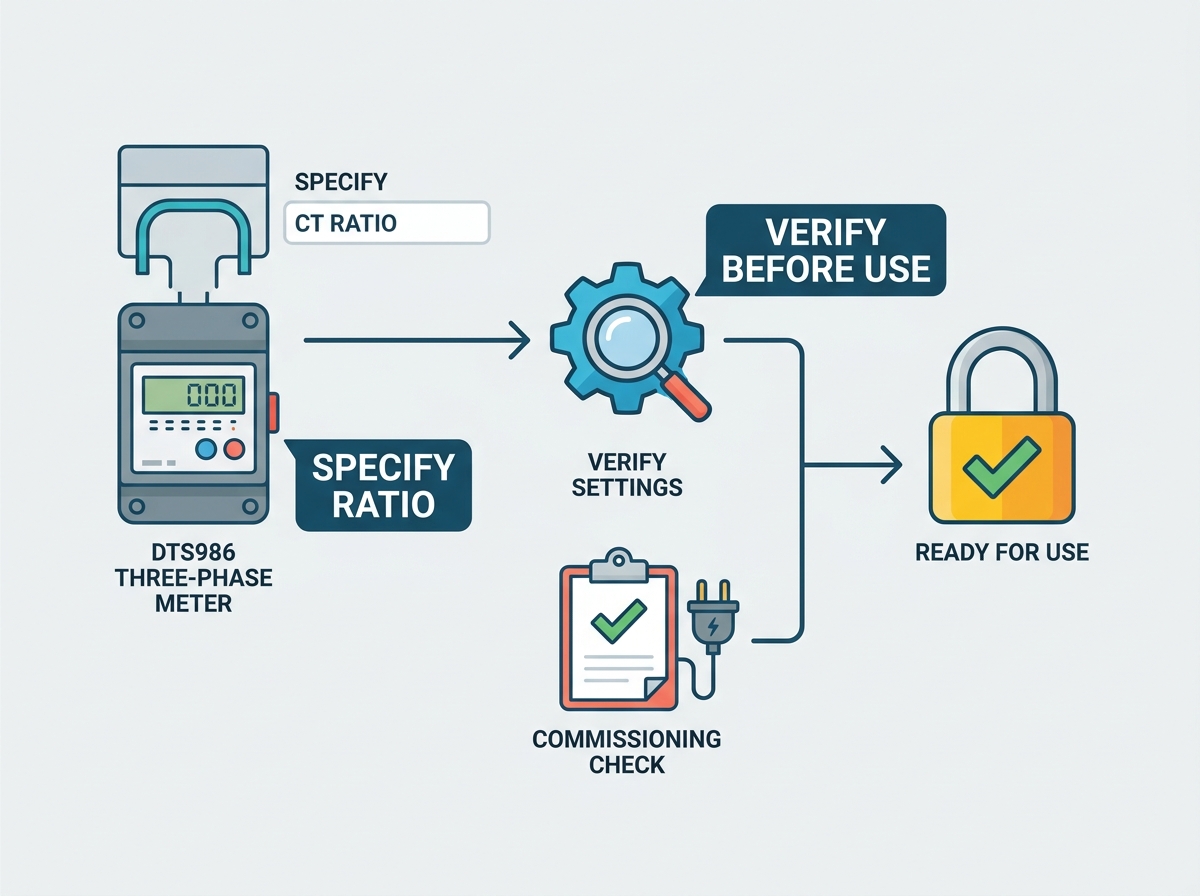
Technical parameters must be locked in during procurement. Vague purchase orders cause commissioning delays. You must establish strict evaluation dimensions before issuing any PO.
Your PO must list mandatory specifications clearly. Missing data leads to contractor assumptions, which inevitably lead to hardware mismatches.
Specify the exact Primary and Secondary Ratio (e.g., 1200:5).
Define the required Burden in VA (e.g., 15 VA).
State the Accuracy Class based on IEC or IEEE standards (e.g., Class 0.2S).
List the System Voltage and Frequency to ensure insulation ratings match the panel.
Provide exact Window Size or Bar Dimensions to guarantee physical fitment over the busbars.
Differentiate strictly between metering CTs and protection CTs. Metering CTs are designed to saturate during fault conditions. This saturation limits the secondary current, protecting the delicate meter inputs. Protection CTs are designed never to saturate. They push massive fault currents to trip relays. Installing a protection CT on a metering circuit guarantees equipment destruction during a short circuit.
Establish a rigid protocol for nameplate auditing. Cross-reference the manufacturer's physical CT nameplate data with your procurement specs. Do this before installation begins. Once the CT sits inside a live panel, reading the nameplate becomes impossible.
Treat this auditing as a mandatory discovery phase. Contractors frequently substitute components based on local availability. An undocumented switch from a Class 0.2S to a Class 1 CT ruins your energy data. Document every serial number and ratio photographically. Keep these photos in the facility's permanent maintenance log.
Oversizing CTs remains a chronic industry problem. Engineers often size CTs for future expansion. Operating a 2000A CT on a 200A load forces the transformer into the low end of its accuracy curve. Measurement precision degrades rapidly here.
Undersizing creates physical danger. A CT running above its rated continuous current overheats. The insulation breaks down. Thermal damage leads to catastrophic failure. You must also specify dielectric strength. Ensure the thermal short-time current rating matches the panel's fault capacity.
Theoretical specs mean nothing without physical proof. Field testing proves the three-phase energy meter works as designed. You must transition from documentation to active verification.
Current flows in a specific direction. CTs have strict orientation rules. The primary side features P1/P2 (or H1/H2) markings. The secondary side features S1/S2 (or X1/X2) markings. P1 must face the power source. P2 must face the load. Reversing this orientation causes the meter to subtract power.
Phase association is equally critical. The CT on Phase A must wire directly to the Phase A current input on the meter. Cross-phasing occurs when Phase A's CT lands on Phase B's input. The meter calculates power using mismatched voltage and current vectors. The resulting kWh data is mathematically useless.
Trace the secondary wires from the Phase A CT directly to the shorting block.
Verify the wire colors match the facility standard for Phase A.
Ring out the wires with a multimeter to confirm continuity from the block to the meter's Phase A input terminals.
Repeat this exact process for Phase B and Phase C.
Use advanced diagnostic tools to hunt for hidden bugs. Portable power quality analyzers act as search operators for your electrical system. They map out the exact vector relationships in real-time.
Read the phasor diagram on your analyzer. It instantly identifies backward CTs. A reversed polarity CT shows a current vector 180 degrees out of phase with its voltage reference. Cross-phased CTs show current vectors misaligned by 120 degrees. You fix these wiring bugs before the facility goes live. Do not rely on the meter's basic display to catch vector errors.
Testing methodologies dictate your level of certainty. Secondary injection testing uses a calibrated source to push 1A or 5A directly into the meter. It proves the meter firmware and the secondary wiring. It does not prove the CT ratio or the physical polarity.
Primary injection testing is the only definitive method. Technicians use massive test sets to push hundreds of amps through the primary busbar. They measure the secondary output and verify the meter display simultaneously. This proves the entire circuit. It requires operational downtime and heavy equipment, but it guarantees absolute integrity.
Isolate and de-energize the switchgear completely.
Connect the high-current test set cables across the primary busbar for Phase A.
Inject a known current, such as 500A, into the busbar.
Measure the secondary current at the shorting block using a calibrated clamp meter.
Verify the meter display registers exactly 500A on Phase A.
The final check happens in the software. You must ensure the physical ratio matches the programmed ratio in the meter's firmware. Navigate to the CT configuration menu. Confirm the primary and secondary values.
Verify the instantaneous kW readings against a known load. Turn on a specific motor or heater bank. Calculate the expected kW draw. Check the meter display. If the reading is off by a factor of 10, your multiplier is missing a decimal place. Fix it immediately.
CT-operated systems carry severe safety hazards. Long-term degradation also threatens data accuracy. You must implement strict mitigation strategies to protect personnel and equipment.
Never leave a CT secondary circuit open while the primary is energized. This is a lethal hazard. An open secondary forces the CT to act as a step-up transformer. It generates thousands of volts across the open terminals instantly.
This voltage spike destroys the CT insulation. It causes arcing, fires, and potential explosions. It can kill technicians instantly. You must mandate the use of shorting terminal blocks. These blocks allow technicians to safely short the secondary circuit before removing the meter for maintenance. The shorting block provides a safe path for the induced current to flow, keeping the voltage at zero.
Modern facilities run on non-linear loads. Variable Frequency Drives (VFDs) and LED lighting generate massive Total Harmonic Distortion (THD). High frequency harmonics distort the current waveform. They cause premature core saturation in standard CTs.
Specify True RMS meters for these environments. Standard averaging meters fail under high THD. Require CTs specifically rated for high harmonic environments. They feature larger cores and higher saturation limits. This preserves accuracy despite severe waveform distortion and high crest factors.
Magnetic cores degrade over time. Environmental heat and vibration alter the physical properties of the transformer. This causes long-term measurement drift. You must establish a framework for periodic auditing.
Schedule visual inspections annually. Look for thermal discoloration on the CT casing. Check for loose secondary terminals. Perform secondary verification testing every three to five years. Recalibrate or replace units that fall outside their specified accuracy class. Maintain a strict log of all calibration data to track degradation trends over the lifespan of the switchgear.
The accuracy of your indirect measurement system depends entirely on precise execution. Procurement, installation, and programming must align perfectly. A single error in CT ratio specification or wiring polarity ruins your energy data. You must treat the entire metering circuit as a single, integrated instrument.
Audit your current procurement templates to ensure VA burden and accuracy classes are explicitly defined.
Mandate the installation of shorting terminal blocks in all new panel designs to protect maintenance personnel.
Require documented primary injection testing results as a strict condition for final commissioning sign-off.
Implement an annual visual inspection schedule to check for thermal degradation and loose connections.
A: The meter applies the wrong multiplier to the secondary current. This causes a direct proportional billing error. If you program a 400:5 ratio instead of an 800:5 ratio, the meter records exactly half of the actual energy consumed. Your data logging and financial billing become completely invalid.
A: You divide the primary current rating by the secondary current rating. For an 800:5 CT, you divide 800 by 5 to get a multiplier of 160. The meter multiplies its raw internal measurement by 160 to display the actual energy usage on the screen.
A: No. This creates a severe technical incompatibility. Pushing 5A into a meter designed for a 1A maximum input overloads the internal current coils. This causes thermal damage, destroys the meter, and poses a significant fire risk. Always match secondary outputs perfectly.
A: Metering CTs are designed to saturate early during a fault. This limits the secondary current and protects delicate measurement instruments from burning out. Protection CTs maintain linearity during massive faults. They push high currents through the secondary circuit to quickly trip protective relays and breakers.
A: Polarity defines the direction of current flow. If a CT is installed backward (P2 facing the source instead of P1), the meter reads the current as flowing in the opposite direction. The meter will subtract that phase's energy from the total, resulting in artificially low kWh readings.
A: Burden is the total impedance of the secondary circuit, measured in Volt-Amperes (VA). It includes wire resistance and meter impedance. If the actual circuit burden exceeds the CT's rated VA capacity, the transformer core saturates. This immediately degrades the accuracy class and ruins measurement precision.


