


Views: 0 Author: Site Editor Publish Time: 2026-10-24 Origin: Site


Utility providers and electrical contractors constantly battle to secure electrical infrastructure while ensuring reliable consumer access. Poorly specified enclosures lead directly to revenue loss from tampering and high maintenance burdens caused by communication failures. A standardized layout and specification checklist serves as the definitive framework for evaluating and deploying a prepaid meter box that meets strict compliance standards and field-deployment realities.
Balancing anti-tamper security requirements with the necessity for reliable Customer Interface Unit (CIU) connectivity requires precise engineering. Field technicians navigate complex installation environments where signal interference, moisture ingress, and physical vandalism are daily threats. This guide breaks down the requirements for CIU access, multi-point sealing, and proper cable entry to guarantee long-term operational success and grid integrity.
CIU Range Dictates Placement: Effective layouts must account for the strict 10–30 meter communication range limit between the meter and the CIU to prevent pairing failures.
Proper Pairing and Power Protocols: Successful deployment requires strict adherence to step-by-step CIU linking procedures, including smart meter card integration and reliable power supply/battery backup configurations.
Sealing is a Multi-Tiered Requirement: Relying on a single lock is insufficient; utility-grade enclosures require multi-point, tamper-evident sealing mechanisms covering both the main cover and the terminal block.
Cable Entry Defines Lifespan: Bottom-entry cable routing combined with appropriately sized, IP-rated glands is critical to preventing moisture ingress and subsequent short circuits.
Material Selection Drives ROI: Specifying a single-phase SMC meter box offers superior thermal stability and impact resistance compared to legacy metal or basic thermoplastic alternatives.
A successful deployment hinges on three non-negotiable outcomes: zero unauthorized physical access, uninterrupted CIU uptime, and strict adherence to local utility regulations. When an enclosure fails to protect the internal components, utilities face immediate energy theft. Bad actors typically attempt to bypass the meter by shunting the incoming live wire directly to the outgoing load wire. The enclosure must physically block this vector. Conversely, if the enclosure blocks communication signals, consumers cannot monitor their usage or top up their accounts, leading to frustrated users and overloaded support centers. Defining these parameters early ensures the selected hardware matches the environmental demands of the installation site.
Standardized layouts drastically reduce the friction of field deployments. Establishing a baseline layout means technicians spend less time modifying enclosures on-site. Pre-drilled mounting points, standardized DIN rail placements, and uniform cable routing pathways streamline the workflow. This uniformity minimizes material waste and accelerates the commissioning process across large-scale residential developments. Installers require specific tools to execute these standardized layouts correctly:
Calibrated torque screwdrivers to secure terminal connections without stripping threads.
Hydraulic crimping tools for attaching heavy-duty lugs to incoming utility lines.
Utility seal presses to lock down the serialized tamper-evident wire seals.
Digital multimeters to verify voltage drops and confirm stable power before CIU pairing.
The inherent conflict in meter deployment lies in locking down the physical hardware while allowing necessary access. Utilities must secure the main incoming lines and measurement terminals against bypass attempts. However, consumers need visibility into their consumption data, and technicians require access for routine diagnostics. Modern enclosure designs solve this by isolating the measurement components behind secondary, sealed covers within the main box. This layered approach ensures that opening the outer door for basic troubleshooting does not expose the unmetered utility lines to tampering.
Environmental protection dictates the lifespan of the internal electronics. Baseline specifications must mandate specific ingress protection (IP) and impact protection (IK) ratings. Operating temperatures also play a role; the enclosure material must maintain structural integrity under intense UV exposure and extreme thermal cycling without warping or degrading.
Rating Type | Minimum Standard | Field Application and Protection Level |
|---|---|---|
Ingress Protection (IP) | IP54 | Blocks harmful dust accumulation and resists splashing water from any direction. Suitable for protected outdoor walls. |
Ingress Protection (IP) | IP65 | Completely dust-tight and resists low-pressure water jets. Required for fully exposed outdoor pole-mounted installations. |
Impact Protection (IK) | IK08 | Withstands 5 joules of impact. Acceptable for indoor or highly secure residential electrical rooms. |
Impact Protection (IK) | IK10 | Withstands 20 joules of impact. Mandatory for street-level deployments to resist vandalism and accidental blunt force. |
Communication between the main meter and the user interface relies on either Power Line Carrier (PLC) or Radio Frequency (RF) technology. PLC transmits data over the existing electrical wiring, making it highly dependent on the quality of the physical connections and susceptible to noise from heavy appliances. RF communication operates wirelessly but faces limitations from physical barriers. Understanding the specific protocol used by the CIU meter box is the first step in determining where the main enclosure can be safely installed relative to the consumer's living space.
Communication Protocol | Primary Advantage | Primary Vulnerability | Ideal Layout Scenario |
|---|---|---|---|
Power Line Carrier (PLC) | No wireless interference; uses existing copper wiring. | Signal degradation from noisy appliances (e.g., cheap LED drivers, heavy motors). | Direct, short wiring runs in single-family homes with modern electrical panels. |
Radio Frequency (RF) | Independent of wiring quality; easier to retrofit. | Blocked by thick concrete, steel doors, and metal enclosures. | Line-of-sight installations or lightweight residential construction (drywall/wood). |
Field commissioning requires a methodical approach to establish the initial handshake between devices. Rushing this process or attempting to pair devices before stable power is established frequently results in communication lockouts, requiring a full system reset. Technicians must follow a strict sequence:
Unbox the CIU and verify the physical integrity of the battery backups and primary power supplies.
Power the main meter and confirm the voltage is stable across all phases.
Insert the Smart Meter Card into the designated CIU slot to initiate the local network.
Input the specific pairing code provided by the utility provider using the CIU keypad.
Monitor the digital display to confirm the initial handshake and verify that consumption data synchronizes.
Operational range typically maxes out between 10 and 30 meters. Layout guidelines must prioritize line-of-sight for RF systems and direct, uncorrupted wiring paths for PLC systems. Installers must avoid mounting the main enclosure behind thick reinforced concrete walls, steel fire doors, or deep inside subterranean basements. Placing the meter near electromagnetic interference (EMI) sources, such as industrial motors, elevator shafts, or heavy water pumps, will severely degrade signal integrity and cause intermittent CIU dropouts.
In regions with dense multi-tenant housing, a common phenomenon involves users attempting to read or top up their accounts using a neighbor's interface unit. Modern utility protocols combat this through strict 1:1 encrypted pairing. Layouts in shared electrical rooms must account for this by ensuring clear labeling and physical separation of communication lines where possible. Encryption prevents cross-talk, ensuring that a specific CIU only communicates with its designated meter, safely isolating signals even when dozens of units operate within the same physical radius.
Post-deployment truck rolls drain operational resources. To prevent this, technicians must execute field-testing protocols before finalizing the installation location. This involves temporarily powering the meter and the CIU in their intended locations to verify signal strength. If the handshake fails, the installer can adjust the layout—moving the meter to an adjacent wall or elevating the CIU—before drilling mounting holes and applying permanent utility seals.
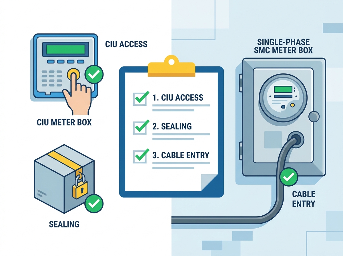
Preventing energy theft requires analyzing how bypasses occur. Bad actors typically target exposed wiring, attempt to drill through the casing to manipulate terminals, or use strong neodymium magnets to interfere with the measurement coils. The enclosure must physically block all three vectors. Security evaluations focus on the rigidity of the door seating, the elimination of pry points along the seams, and the internal compartmentalization that keeps unmetered incoming lines entirely isolated from the consumer-accessible breaker sections.
A single padlock on the outer door provides zero real security. Utility-grade enclosures demand multi-point, tamper-evident sealing. The primary utility seal secures the main enclosure door using serialized plastic pull-tight seals or traditional lead wire seals. Inside, a secondary independent seal locks down the transparent meter terminal cover. A third seal often protects the incoming main circuit breaker. This multi-tiered approach ensures that even if a consumer gains access to the breaker to reset a trip, they cannot access the live utility terminals without breaking a registered, serialized seal.
Enclosure designs force a choice between transparent viewing windows and fully opaque doors. Polycarbonate viewing windows allow meter readers and consumers to visually inspect consumption data and diagnostic LED lights without breaking the main utility seal. This reduces unnecessary maintenance calls. However, fully opaque, reinforced doors offer superior IK10 impact resistance. The optimal layout often utilizes an opaque main body with a small, heavily reinforced, scratch-resistant window positioned exactly over the meter's digital display. These windows must be ultrasonically welded or mechanically fastened from the inside to prevent push-in attacks.
Exposed hinges represent a failure point; a simple hammer and punch can remove the pins, allowing the door to be bypassed entirely regardless of the lock. Utility enclosures must feature internally concealed hinges. Locking mechanisms must utilize non-corrosive materials like brass or marine-grade stainless steel to prevent seizing over time. The lock housing itself should be recessed or shielded to resist drill bits and heavy pry bars.
Poor wiring layouts directly accelerate enclosure degradation. When cables are forced into tight bends or routed improperly, the insulation stresses and eventually cracks. This leads to arcing, carbon tracking, and severe fire hazards. Disorganized internal wiring makes routine maintenance dangerous for technicians, increasing the risk of accidental contact with live phases during simple breaker replacements. Proper cable management ensures that the bend radius of heavy utility cables is respected, preventing mechanical stress on the meter terminals.
Gravity is the ultimate enemy of electrical enclosures. Top-entry cable routing invites disaster; water naturally runs down the exterior of the cable, pools at the entry point, and eventually breaches the seal, dripping directly onto live terminals through capillary action. Bottom-entry layouts utilize gravity to keep water away from the entry points. Any moisture running down the cable drips off before reaching the gland. Top-entry should be strictly avoided in all outdoor or damp environments.
Selecting the correct cable glands maintains the enclosure's IP rating. A gland that is too large allows moisture and insects to enter; one that is too small damages the cable insulation during installation. Properly torqued glands provide essential strain relief, ensuring that external pulls or heavy winds do not transfer mechanical stress directly to the sensitive meter terminals. A standard gland consists of a locknut, washer, seal insert, claw, and dome nut, all of which must be sized accurately to the cable's outer diameter.
Cable Type | Typical Outer Diameter (OD) | Recommended Metric Gland Size |
|---|---|---|
10mm² Single Core (Copper) | 6.0mm - 8.0mm | M16 |
16mm² Single Core (Copper) | 7.5mm - 9.5mm | M20 |
25mm² Single Core (Aluminum) | 9.0mm - 11.5mm | M25 |
Multi-Core Communication Cable | 4.0mm - 6.5mm | M12 |
Internal layout dictates thermal management. Meters and circuit breakers generate heat under heavy loads. The enclosure must provide adequate minimum clearance between components to allow for passive air circulation. Incoming unmetered lines must be physically separated from outgoing metered lines to prevent inductive cross-talk and simplify visual inspections. Clear pathways ensure technicians can trace faults rapidly without untangling a nest of overlapping wires.
Material selection dictates the durability, safety, and lifespan of the installation. Engineers must evaluate materials based on their ability to withstand environmental degradation, their inherent electrical insulation properties, and their resistance to physical impacts. The right material minimizes maintenance cycles and eliminates the need for premature replacements.
Material Type | Insulation Class | UV Resistance | Impact Rating (IK) | Best Use Case |
|---|---|---|---|---|
SMC (Fiberglass) | Class II (Double Insulated) | Excellent (No degradation) | IK10 | Harsh outdoor, utility-scale deployments |
Polycarbonate | Class II | Moderate (Yellows over time) | IK08 - IK09 | Indoor, protected residential areas |
Metal (Steel/Aluminum) | Class I (Requires Earthing) | N/A (Prone to rust) | IK10 | Obsolete for modern prepaid systems |
Sheet Molding Compound (SMC) represents the apex of enclosure materials. Specifying a single-phase SMC meter box provides Class II double insulation, completely eliminating the need for internal earthing wires and protecting technicians from electrocution if a live wire touches the inner wall. SMC is manufactured by compressing glass fibers mixed with polyester resin under extreme heat, resulting in a composite that is inherently UV resistant. It maintains its structural integrity and color after decades of direct sunlight. Furthermore, it features self-extinguishing fire properties, containing any internal electrical fires before they spread to the surrounding structure.
High-grade polycarbonate remains acceptable for specific applications. It is lightweight, easy to machine on-site, and offers excellent transparency for viewing windows. However, its long-term performance outdoors is inferior to SMC. Prolonged UV exposure causes polycarbonate to yellow, become brittle, and eventually crack under minor impacts. It should be restricted to indoor installations, shaded corridors, or highly protected environments where direct sunlight is not a factor.
Legacy metal boxes are obsolete for modern prepaid deployments. Metal conducts electricity, requiring strict earthing protocols. If the earth connection fails due to a loose lug or severed wire, the entire outer casing becomes a lethal electrocution hazard. Metal is highly susceptible to galvanic corrosion and rust, especially in coastal or high-humidity regions. The maintenance burden of repainting and replacing rusted hinges makes metal an unviable option for forward-looking utility infrastructure.
Field mistakes compromise the best-designed enclosures. Over-tightening mounting screws using impact drivers instead of calibrated hand tools is a frequent error that creates micro-cracks in the backplate, destroying the IP rating. Installers often bypass cable glands entirely, pushing raw cables through jagged drilled holes, guaranteeing future water ingress. Another failure is sealing the box before verifying the CIU pairing, forcing the technician to immediately break the new utility seal to troubleshoot the connection.
Mitigating these risks requires a rapid, step-by-step field checklist. Technicians must follow these procedures to ensure compliance and operational stability:
Verify the physical layout and ensure the location falls within the 10-30 meter CIU range.
Drill mounting holes precisely and use rubber washers to maintain water tightness against the wall.
Route cables strictly through bottom-entry IP-rated glands, ensuring the dome nut is torqued correctly.
Power the system and confirm the CIU communication handshake before closing the inner covers.
Apply the serialized utility seals to the terminal cover and main door, recording the seal numbers in the deployment log.
Installing multiple units in a single electrical room introduces unique challenges. Cable management becomes critical; incoming utility feeds must be neatly trunked and separated from the outgoing residential loads. Installers must adhere to strict labeling protocols, ensuring each meter is clearly matched to its corresponding apartment and CIU. Proper spatial layout prevents thermal overloading in the room and ensures that technicians have adequate physical clearance to safely operate on individual units without disrupting adjacent power supplies.
A secure, reliable deployment relies equally on advanced material strength and strict adherence to layout rules. Enclosures must protect against environmental threats while facilitating seamless communication between the meter and the consumer interface. To execute a flawless rollout, engineering and procurement teams must take the following actions:
Download detailed technical specification sheets for SMC enclosures to verify compliance with local utility mandates regarding IP/IK ratings.
Audit existing field installations to identify and replace top-entry cable routing with bottom-entry designs to prevent water ingress.
Update contractor training manuals with strict 1:1 encrypted CIU pairing protocols to eliminate cross-talk in high-density housing.
Engage directly with enclosure manufacturers to customize internal layouts, ensuring the hardware matches the exact dimensions of the selected prepaid meters and breakers.
A: The communication range typically spans between 10 and 30 meters. This limit depends heavily on the technology used—Power Line Carrier (PLC) or Radio Frequency (RF)—and the presence of physical obstructions like thick concrete walls or electromagnetic interference.
A: First, ensure the CIU has stable power via batteries or an outlet. Insert the smart meter card if your system requires one. Finally, input the specific pairing code provided by your utility provider using the keypad to establish the secure handshake.
A: No. Modern utility protocols require secure, 1:1 encrypted pairing between the meter and the CIU. This prevents cross-talk, ensures data privacy, and blocks unauthorized access in multi-tenant buildings.
A: SMC offers Class II double insulation, eliminating electrocution risks without needing an earth wire. It is completely immune to rust, highly UV resistant, and features self-extinguishing properties, offering a vastly superior lifespan compared to metal.
A: Yes, provided it is explicitly designed for outdoor use. It must feature an IP54 or higher rating to block rain and dust, utilize UV-stabilized materials like SMC, and incorporate bottom-entry cable routing to prevent water pooling.
A: Utility-grade security requires multi-point sealing. This includes independent, tamper-evident serialized seals on the main outer door, the internal meter terminal cover, and the circuit breaker access compartment.
A: Always utilize bottom cable entry routing so gravity pulls water away from the box. Additionally, use properly sized, IP-rated cable glands for all entry and exit points, and never drill unsealed holes in the top of the enclosure.


